Circuits and Power and Networks, Oh my: Making Art for Napa Lighted Arts Part 4
Hey friends, we’re back again with more stories to tell. Today we’re going to discuss the PF3000‘s insides, which isn’t really any one single “thing” but rather a collection of smaller enhancements. For all this to make sense I will finally go into the general circuitry architecture of the piece, but I’ll keep things at a high level. While an art piece may have some big story arcs as we saw in part 1, part 2, and part 3, there are plenty of subplots going on; I’m excited to finally share them with you all.
To recap, in order to prepare our award winning PF3000 for the 2026 Napa Lighted Arts festival we had to make the PF3000 ready for the public and ready for the weather. We call the enhancements to the art piece for Napa Lighted Arts version 2 which has been a collection of projects both big and small. So far we’ve covered 3 big beats: part 1 discussed our new storm-ready frame, part 2 dived into the world of capacitive touch, and part 3 was about how we used 3d printing to water proof the front of the PF3000.
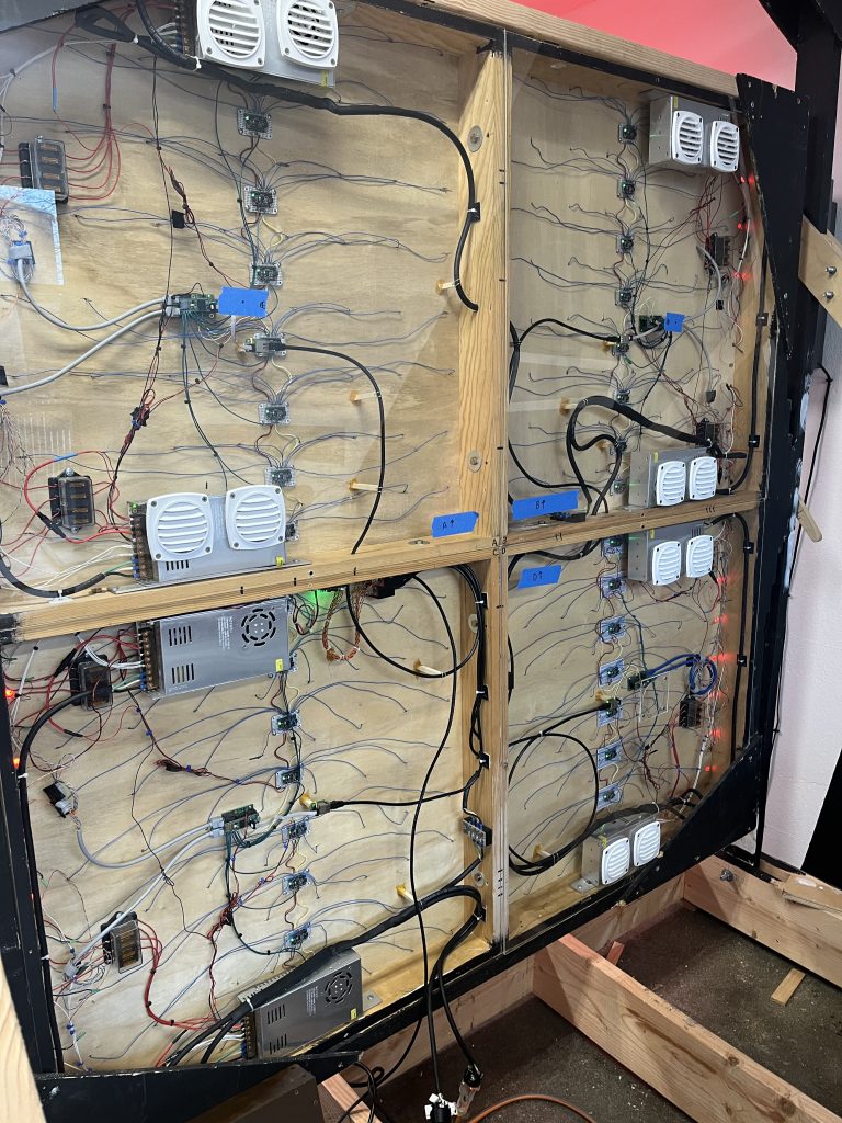
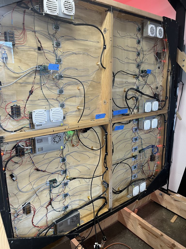
We’ve talked about a lot about the PF3000’s front but not so much about the back and yet the back is where the magic happens. There’s an incredible architecture that provides all kinds of necessary facilities for the art piece. Although you can’t see the PF3000’s rear end at the Napa installation, it is quite beautiful and looks a lot like a human’s central nervous system (imho/ymmv). Don’t worry though, you’ll be able to see it right here; I took plenty of pictures and will walk you through some more of the really cool things we did for the PF3000 version 2.
Other Articles in this series:
- PF3000 v2’s New Frame: Making Art for Napa Lighted Arts Part 1
- PF3000 v2’s Touch Sensors: Making Art for Napa Lighted Arts Part 2
- 3D Printing the Lattice: Making Art for Napa Lighted Arts Part 3
- Build Day: Making Art for Napa Lighted Arts Part 5
PF3000 Infrastructure Design
4 Tiles and a Controller
In order to understand why we did the work we did some context is helpful. I’d like to take a brief moment to discuss the PF3000’s electronics infrastructure from a high level and then we will zoom in.
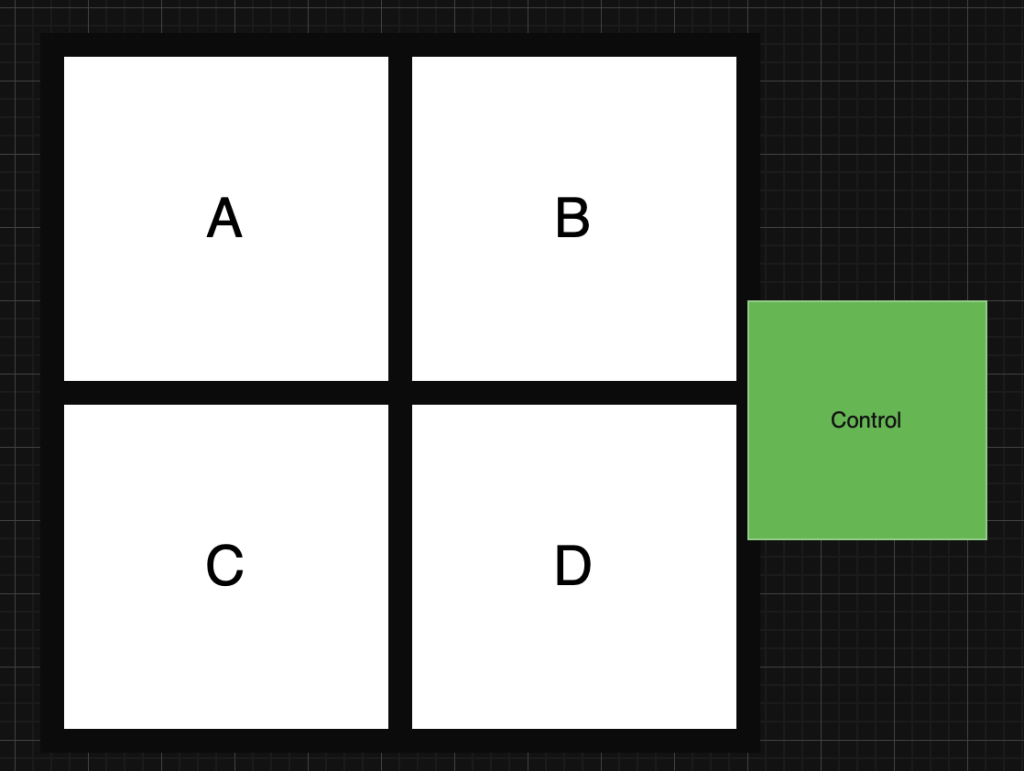
The PF3000 touch screen is comprised of four quadrants or “tiles” (they’re called tiles on purpose, keep reading). In the picture above, these are labeled A, B, C, and D. Each tile is an 8×8 grid of pixels (our 4″x4″ touch pixels to be exact) and a tile can run independently from the other tiles; this implies that each tile has its own electronics infrastructure. On the right of the image is the primary controller which I will explain later.
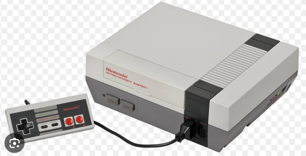
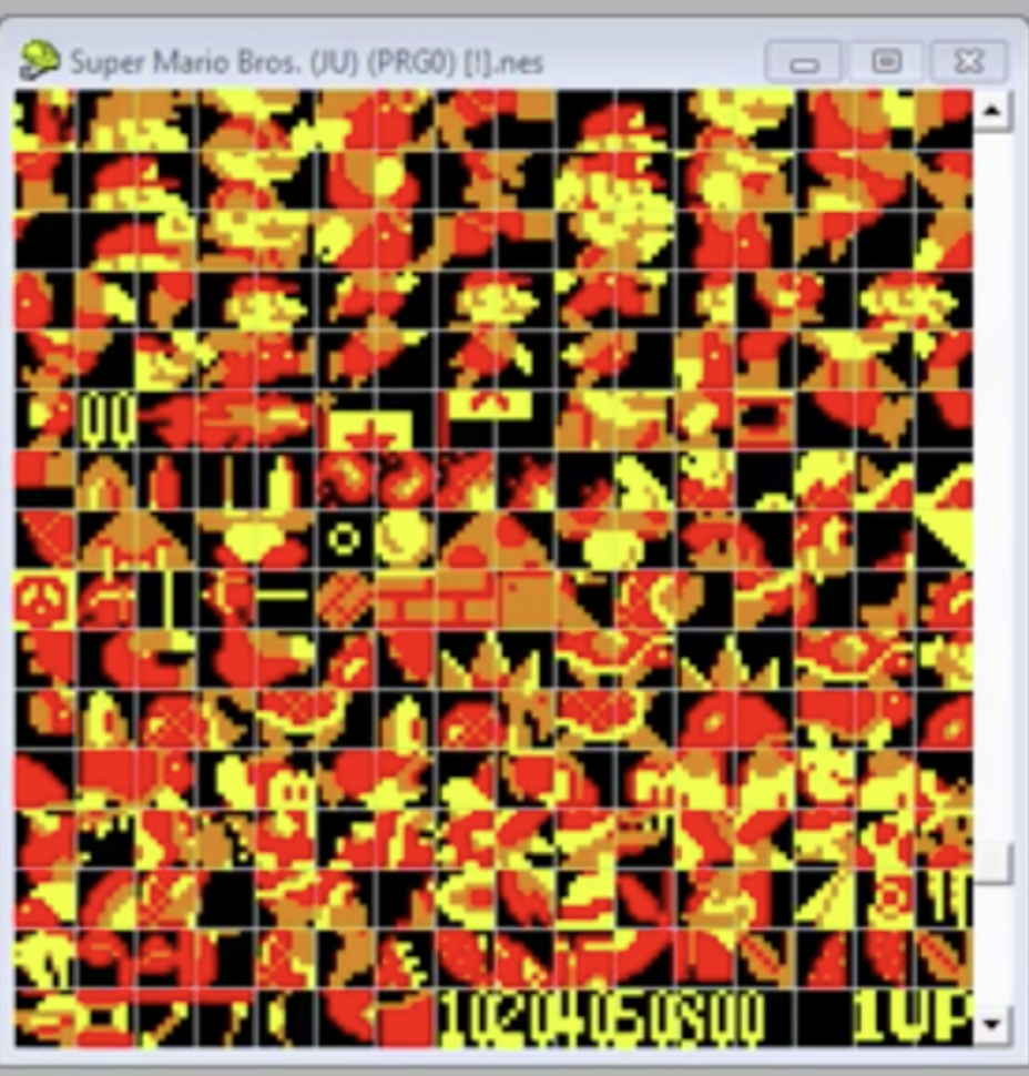
There are a few reasons we chose to design the PF3000 this way though the one of the main reasons has to do with the NES or Nintendo entertainment system (famicom in Japan) and how the PF3000 is actually designed around vintage video game consoles. Without going into too much detail, the NES draws images on your TV using a tile based system, where a tile aggregates several pixels. This is because that old 8-bit hardware didn’t have a lot of power and so it couldn’t really handle managing all the pixels individually. To get around this, the NES designers packed graphics into 8×8 pixel grids called tiles and then the NES managed much fewer of these tiles. Because we love the NES we made the PF3000 do this too.
There are practical reasons for this design as well.
- Having 4 tiles also makes it easier to move the PF3000. When all 4 tiles are connected, the PF3000 is heavy, really heavy. What’s less heavy? One fourth of the PF3000.
- Dividing the system into 4 tiles means one tile can fail without impacting the other tiles.
- Size is a thing too. We wanted to be able to get the art piece into a standard SUV for travel which is pretty hard to do with a 6’x6′ square. By breaking the piece into tiles it stacks quite nicely
- You can do development on only a single tile and then replicate it to the other tiles later which makes working on the PF3000 a lot easier.
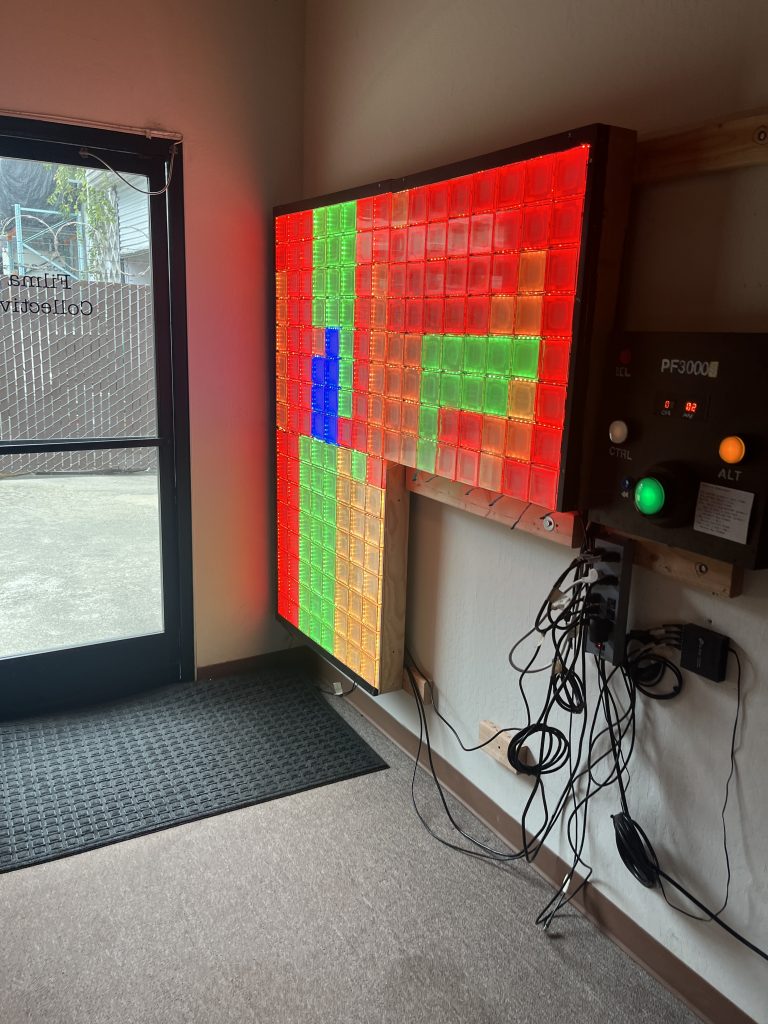
The last piece to mention here is the controller. It actually has two functions:
- Aggregate and coordinate the colors and state of the four tiles
- Provide a human interface for an animation workflow
We’re not going to dive into the controller too heavily but its important to know that its there and that is connected to the tiles.
Tile Design
Let’s zoom in now to a single tile; there’s a lot of stuff in there. Each tile is exactly the same so once we understand one tile we understand all the tiles.
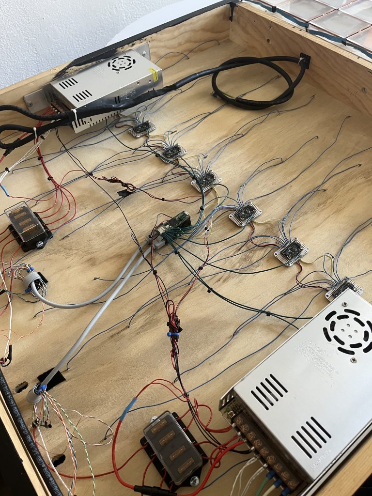
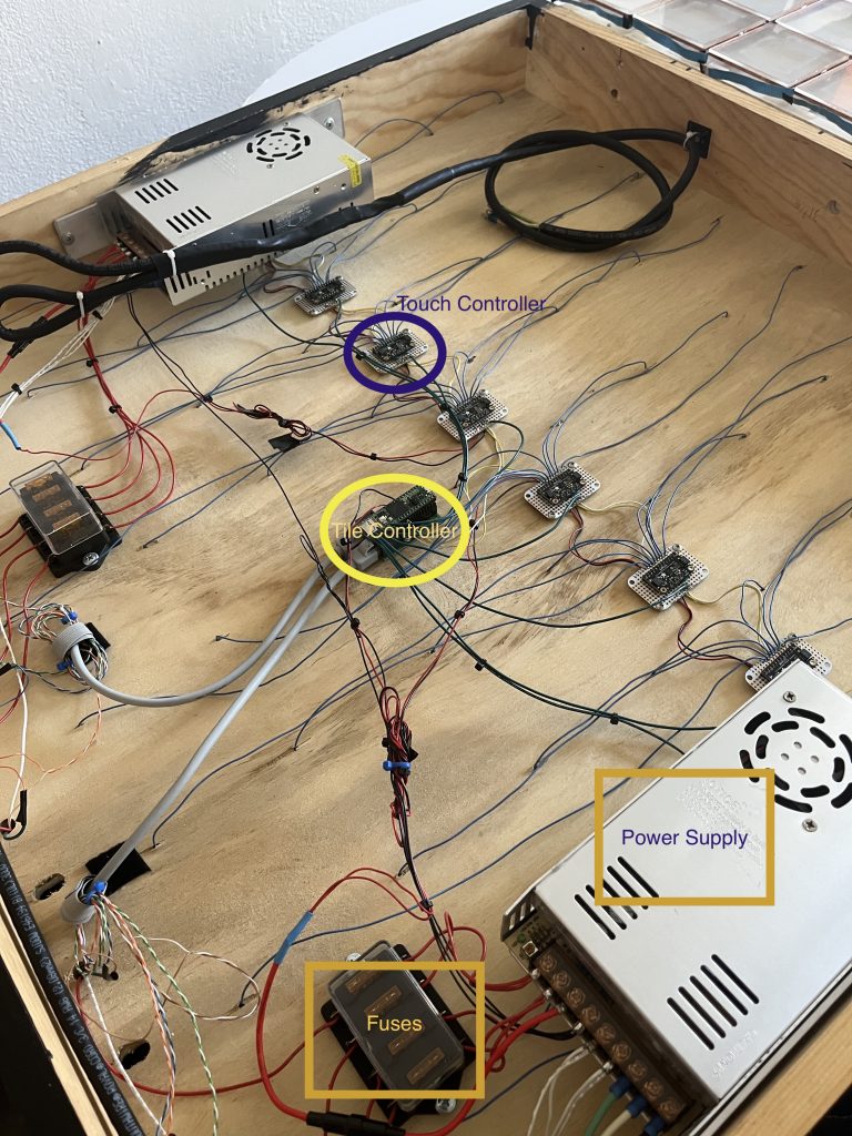
The image above is from an in-progress tile. Inside there is a bunch of stuff:
- Power Infrastructure – just regular old electricity
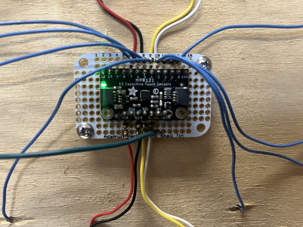
- Touch Controllers – the central nervous system, these determine if someone is touching a pixel or not.
- Tile Controller – this communicates with the touch controllers and tells primary controller when and where touches occur. After informing the primary controller what is happening, the primary controller will instruct the tile controller what color a pixel should be.
I’m going to draw another diagram for you to help you understand how things are laid out.
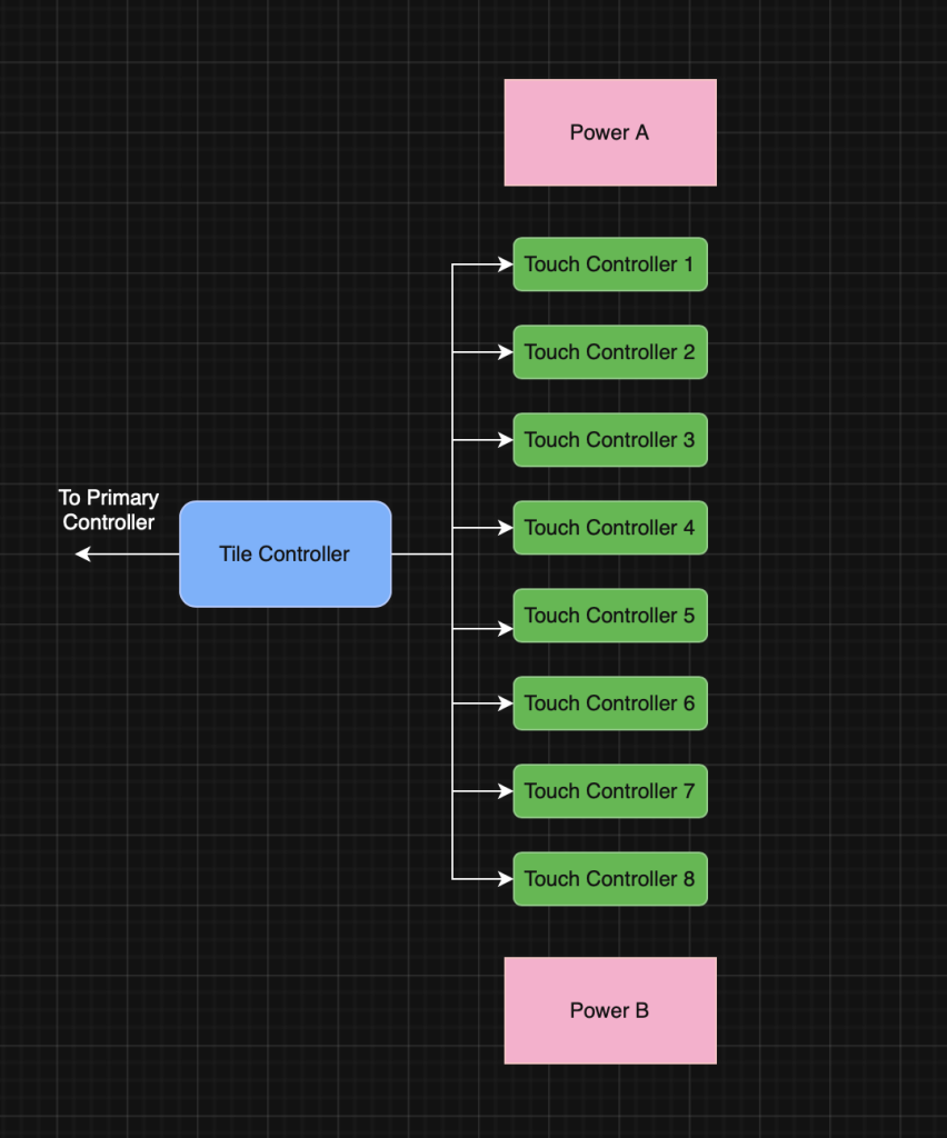
Breaking down this diagram even further:
- Each tile has two power supplies. Each power supply provides electricity for half of the tile (4×8 pixels) which is both the LEDs and the circuitry. While the circuity is generally low power, the LEDs use quite a bit of power, especially when they are displaying white. Power supplies also have supporting infrastructure like fuses. These are the pink rectangles labeled POWER in the diagram above
- Each tile has 8 touch controllers, there is 1 controller per row of pixels and there are 8 rows of pixels per tile. A touch controller can technically manage up to 12 pixels but its a little easier to wire to a row of 8 pixels.
- A touch controller will have 1 wire for each touch pixel. In the photographs these are the blue wires. These wires go through the rear of the PF3000 to the front and are soldered to each of the 4″x4″ large pixels.
- Each tile has 1 tile controller. It communicates with the touch controllers and the primary controller. This controller is also responsible for turning on lights and setting the colors for the lights.
- The tile controller communicates to the primary controller using a standard pc-style network a la ethernet. Each controller has a network address and is connected to a network switch, much like your computer.
- The tile controller has to manage data lines to the LEDs to control the color. We found ethernet cables to be convenient here however we had to modify them for the LED strips and they are very much not ethernet in this context, just wires and connectors we found straight forward to use. Even though they look like ethernet cables on one side they are actually fully customized for driving LED data.
I’ve annotated the picture below to help you identify components.
Another photo, just for fun.
Changes for Version 2
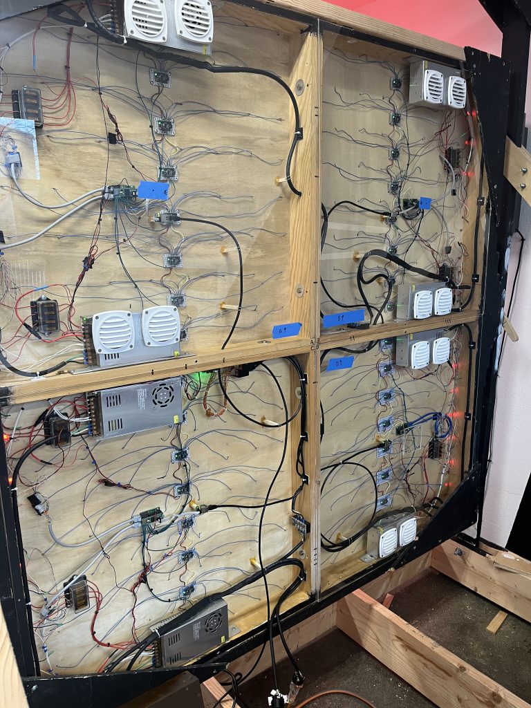
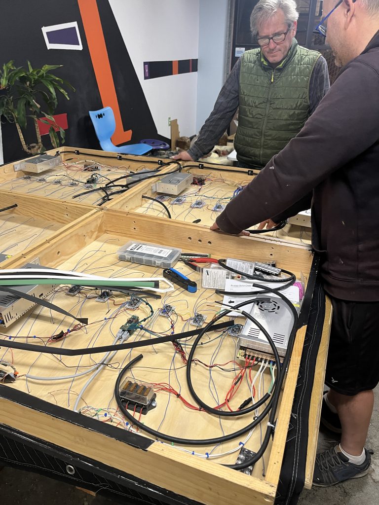
Now that you have an idea of what we’re working with we can talk about some of the version 2 changes and hopefully they will make more sense. There are quite a few changes. We’ll start you off with close-to-the final product; the image below has 3 out of 4 tiles complete.
Waterproofing and Heat management
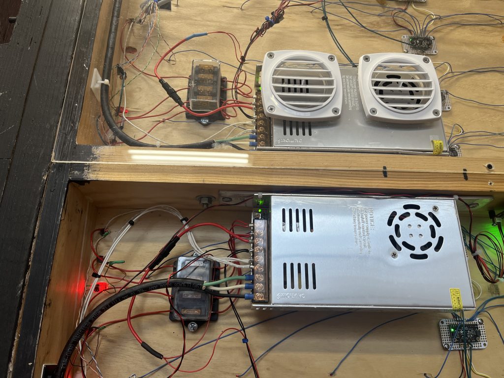
Much like the front of the PF3000 we needed to ensure that water did not enter through the rear. We managed this by using custom cut acrylic and then applying sealant around the acrylic’s edges.
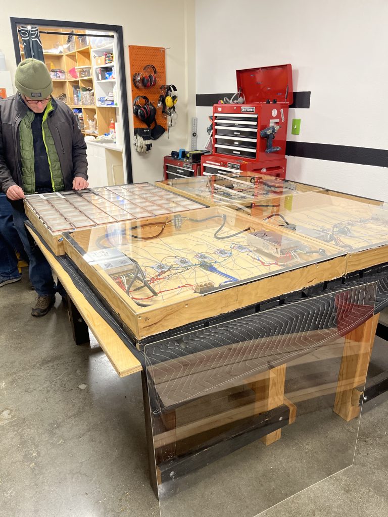
This wasn’t everything though as we also had to manage heat for the power supplies. Heat management requires a cool air intake and a hot air exhaust and this has to be done for each power supply. Air circulation requires us to puncture the acrylic and so we also needed to add weather exhaust hardware similar to what you might find in a typical home.
Power and Network Cleanup
In the original PF3000, each power supply had its own wall plug as did the controller and the network switch. This meant that the PF3000 required a massive 10 plugs. There was also a network switch for all the ethernet connections. You can see the mess in the picture below.
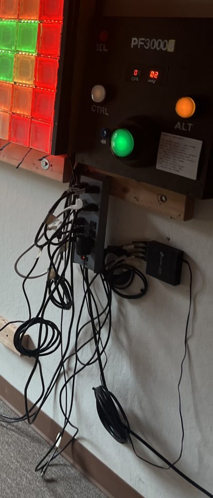
Since we typically did short term installations we could just cover this nightmare with a tarp. For a longer term public installation this isn’t going to cut it for a bunch of reasons. We knew we had to internalize much of this infrastructure to the PF3000 so this wouldn’t be accessible to the public or the weather. The ultimate goal was to have a single external power plug and as few cables outside the PF3000 as humanly possible.
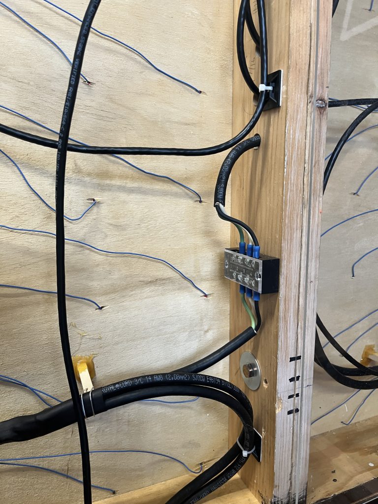
Power Cabling
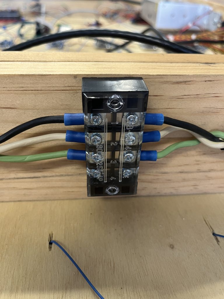
Starting with the power supplies, we were able to connect the power supplies in serial (meaning one power supply connects to the next in series, like a daisy chain). We installed some extra hardware so we could easily undo all the power connections if when we took the tiles apart.
Shrinking the Network Hardware
On the network side of things we just needed to clean up our little switch since we can’t have it sitting outside the PF3000. Its this thing from the picture above:
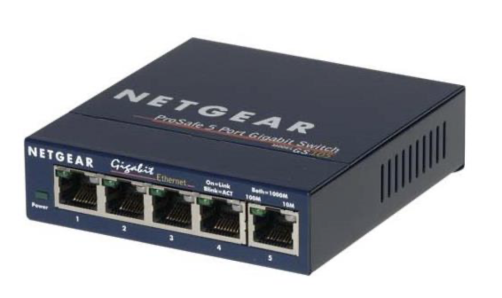
We tried a bunch of ideas to just shove this puppy into the rear. Unfortunately it was just a little too long/wide for any kind of reasonably good fit. Eventually we gave up on using this monstrosity and I decided I would see if I could find the world’s smallest ethernet switch out on the internet. Sure enough, I did.
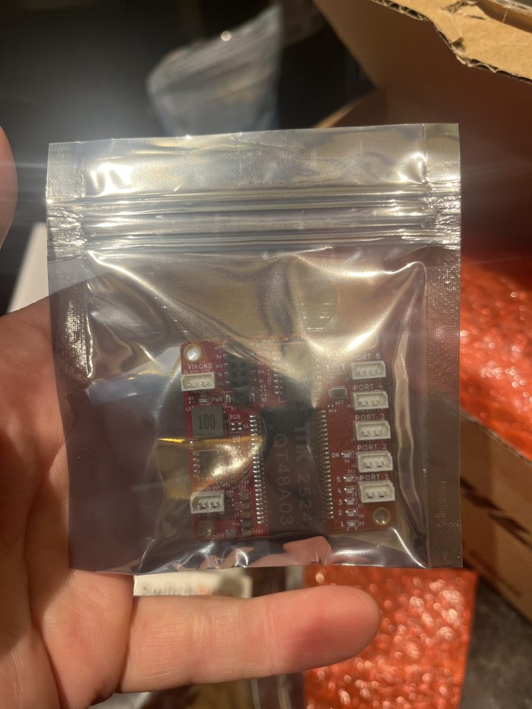
Turns out the smallest ethernet switch I could find was pretty small. There’s a US company called BotBlox that makes ethernet for embedding in robots, drones, things like that. This turned out to be exactly what we needed. Now this little unit doesn’t provide the typical ethernet adapters, these are known as RJ45 btw, so we bought some ethernet couplers and 3D printed a small harness to mount them into the frame.
Crosstalk
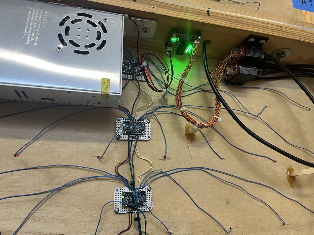
Time for a real quick and dirty education session on something we engineers know as crosstalk. The tl;dr is that when you’ve got a bunch of wires next to each other they can induce signals in nearby wires. When this happens a signal on a wire is effectively altered and sometimes this ruins your day. Crosstalk and the physics behind it is way beyond the scope of this article but you can begin to learn about it on the wikipedia.
Now we weren’t exactly experiencing a high volume of crosstalk. That said, we are also pushing the limits of what we can do with capacitive touch and anything that degrades the touch signals would be a problem. Looking at the wires in our design we have all kinds of stuff going on, power, network, and then some. The probability of crosstalk causing a problem for us we felt was high.
We decided we should err on the side of caution and separate as many of these cables as we can from the touch sensor wiring. To do this we propped up any cabling that was not for touch sensing on a little pole to provide physical distance between it and the more sensitive wiring we had.
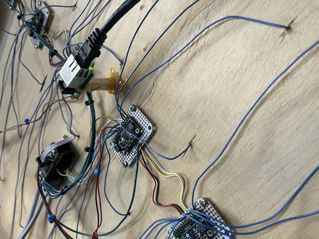
These little poles are holding up all kinds of wires in the rear of the PF3000. If you scroll up and look through some of the pictures I’ve already posted you will surely see more of them.
Wrapping Up
Believe it or not folks, even after 4 parts and all the stories, this isn’t everything that went on during the development of PF3000 version 2. We have more small changes and stories to share, though not in this article; maybe they would be better suited for a chat sometime. I will leave you with an image we’ve already shown, but now you have the context to know what you’re looking at. Look forward to part 5 soon which I think will be the final entry in this series.